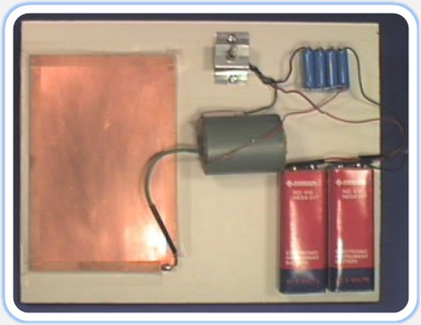
The Kirlian device we are building uses a HV transformer. It is battery powered, but don't let that lull you into a false sense of safety. The Kirlian device generates pulses of high voltage that can provide a nasty shock. Still an advantage of being battery powered is portability.
In addition we will build a transparent electrode that allows one to use a standard camera (with bulb setting) to capture Kirlian images.
The schematic is shown in Figure 2. A completed circuit can be seen below the schematic. This is a simple manual device. It uses very few components. You would be hard pressed to find a simpler device that works as well. The prototype is built on a single piece of wood measuring *" x 10" x ¾" thick (see photo). The batteries B1 and B2 are 67.5-volt photo (instrument) batteries wired in series to produce 135 volts.

Figure 2

If the photo batteries are not available you may want to try wiring 10 or more 9-volt batteries in series. The discharge will not be as intense, but it will work. Another option is to take the output from a 120V/24V step down transformer connected to a voltage quadrupler. With the 24V (AC) output wired to a voltage multiplier (4x), the unit should produce about 100 volts that can be used for the power supply for this Kirlian device.
The capacitors C1-C4 are wired in parallel as shown in Figure 2.
The transformer T1 is a high voltage auto-transformer. Auto as in self-inductive, not auto, like automobile. The T1 transformer has three wires coming out of it: two enamel wires and one green insulated wire from the center. The green insulated wire is the high voltage wire that connects to the discharge plate. The two enamel wires are the primary wires that are connected to switch SW1. There is no polarity with the enamel wires. So it doesn't matter which enamel wire is connected to the switch, and which is connected to the capacitors. Either way the circuit will function properly.

Figure 3
The toggle switch SW1 is a single pole double throw "momentary" contact. The switch has solder wires on the bottom, see Figure 3. This particular switch doesn't lock or stay in the opposite position. A built in spring immediately brings the switch back to its original position. To operate the device, toggle the switch on and off. When the switch is in the "on" position, it closes a current path to the HV transformer and capacitor bank.
The switch is important and must be wired correctly to obtain maximum benefit. Looking at the schematic shows how the switch appears in its resting state. In the resting state the batteries are disconnected from the circuit. This preserves the life of the batteries. Also the discharge path from the capacitors is closed. This prevents a potential shock hazard from being stored in the capacitors, to be unleashed on an unsuspecting experimenter.
To mount the switch to the board a metal battery clip (9-volt) is used, see parts list. The clip is bent to make a U shape as shown in Figure 3. The center hole in the clip is enlarged to fit the switch SW1. A hole is drilled in each ear of the clip to secure it to the board with two wood screws. The switch is secured to the clip, and then the assembly is secured to the board.
Below is an example of a photograph taken with the Kirlian device.
